Monday, April 13, 2020

Sending Room Temperature and Humidity Data to Google Cloud


In the last Blog Using Google Cloud IoT Core Platform with a Raspberry Pi, we have seen How to connect the Raspberry Pi as Device Gateway to the Goole IoT Platform. We were able to connect the LED and able to configure the status of LED from Google IoT service. 

In this blog Using the DHT sensor data like humidity and temperature can be collected from the room environment. This sensor data are given to connected Raspberry Pi and then sends this sensor information to the Google IoT Platform using the MQTT Bridge protocol.


Cloud IoT Core is a fully managed service that allows you to easily and securely connect, manage, and ingest data from millions of globally dispersed devices This Device gateway will send the sensor data to the google cloud platform for data storage and processing which can be further use in may services related to IoT.


Hardware Requirement:
  • Raspberry Pi 3 Model.
  • DHT11 Sensor.
  • Jumper Wire
Software Tool Requirement:
  • Xshell Software
  • WinSCP
  • Openssl 
  • Python3

Circuit Diagram:

In this circuit diagram, Raspberry Pi will collect the room temperature and humidity information using the DHT sensor connected via the GPIO pin. Python program running on Raspberry pi will read this sensor information and send it to the Google Cloud using the MQTT protocol (MQTT Bridge).

Please find below basic information related to cloud IoT Project 
  • Create an IoT cloud project and enable Cloud IoT Core and Cloud Pub/Sub APIs (quickstart).
  • Creating registries and devices (Link)
  • Setting up your Raspberry Pi (Tutorial Link).

In my previous blog (Using Google Cloud IoT Core Platform with a Raspberry Pi) I have shown how to connect the Raspberry Pi as Device Gateway with an example of connecting LED light to Google IoT Core.  So I hope you are aware of basic information related to creating the project related to Google IoT core. 


Objective:
  • Create a Device Registry and Device topic.
  • Create Subscription on created device topic.
  • Set up your Raspberry Pi with DHT.
  • Sending DHT sensor data from Device to Google Cloud IoT.
  • Show Received Data with Subscription message.

Create a Device Registry and Device topic:
Let start the below steps to create at least one device registry for this project.


  • Go to google cloud IoT page in the Google cloud console (Link)
  • Then go to the "IoT Core" tab available in the left navigation bar.


    • Click on "Create Registry" to create the new Device Registry "iot-sensor" and  and select the region "asia-east1".

    • Now add the topic to this registry by selecting the option in "Cloud Pub/Sub topics" dropdown. Create the new device "iot_sensor_dht" and then click "Create Topic".

    • Select default HTTP and MQTT protocol.
    • Leave the remaining option as it is and then click below "Create".

    Create a subscription to the registry's Pub/Sub topic:

    Now we will add the new subscription to the created registry topic "iot_sensor_dht".  This is used to subscribe to the data exchange on this device topic.
    • Go to google cloud IoT page in the Google cloud console (Link)
    • Then go to the "Pub/Sub" tab available in the left navigation bar and click on topics.
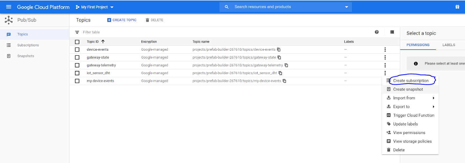

    • Once you click on Create Subscription you need to provide the subscription details for the topic "iot_sensor_dht".
    • Give the subscription name "pub_sub_iot_sensor_dht" send the delivery type to pull to receive data on this device.
    • Leave the remaining option as it is and then click below "Create". 
    • Now we can able to see our subscription name in the Pub/Sub subscription details.
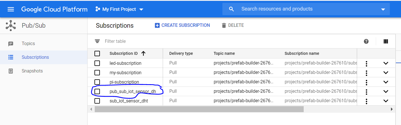

    Now we have successfully created the Device registry "iot_sensor", Device topic "iot_sensor_dht", and subscription "pub_sub_iot_sensor_dht", next step is to send the sensor data to this topic from Raspberry pi. So lets set up and configure Raspberry pi to establish communication with Google IoT.

    Secure Account Service:


    Service account intended to represent user that needs to get authentication and authorizatoin to access google cloud API's or google cloud service. it is a way of secure communication between the google cloud service and the end-user human or non-human. It simplifies the process of authentication of the end-users devices which can be communicated using this secure way of communication by providing authentication and authorization.

    There are different ways to impersonate a service account to access Google APIs:
    • Authentication using RSA private keys (Uses the Encryption Algorithm)
    • Authorization using Cloud IAM policies

    Authorization using Cloud IAM policies: 

    All service accounts have Cloud IAM policies that grant access to the service account. Some permissions allow users to impersonate, or become, the service account based on the users' credentials.

    Here we will create the service account to access the specific google service need to access the resource by creating Cloud IAM policies. Let's see how to create a service account and download the service account access file.

    • Open Google Cloud Console and then got to the IAM & admin tab available in navigation bar in the left. Click on the "Service Accounts" link.

    • Now create a Service account by clicking on "CREATE SERVICE ACCOUNT" from the IAM & Admin console.


    • Now furnish the details with Name field "serviceaccount" and then click "create"


    • In the next step, we will create the rules to give different access to a user from this service account.  Here we will add roles for "Cloud IoT Admin" and "Pub/Sub-admin" from the Role select bar.
    • Now click on the "Create Key" for the created service account to download the service account file for user.

    • Select the JSON format for the service account file.


    • Service account JSON file will get download to your local directory which will use for authorization and authentication of the device to the google cloud service. Keep this file very securely as it gives you access to your Cloud Service Platform.
    • Now copy this file to your device directory [Raspberry Pi] so that this file can be used in the device program while communication to Google Cloud service.


    • I used WinSCP to copy this JSON file to the Raspberry pi Directory.

     Set up your Raspberry Pi with DHT sensor:


    Connect to your raspberry pi using the SSH connection. Before connecting to Raspberry pi make sure your raspberry pi is connected to a local wifi network and able to access the internet service. Please find details regarding the SSH connection. Once your Raspberry Pi device is in the local network you will be able to access it using VNC Viewer or SSH connection (How to set up WiFi and enable SSH on your Raspberry Pi).
    Here I am using the XHELL software to connect to the raspberry pi using the Wifi IP address assign to the Raspberry Pi device. Provide the connection related information before setting up the ssh connection which includes the username and password credential of Rasberry Pi user.


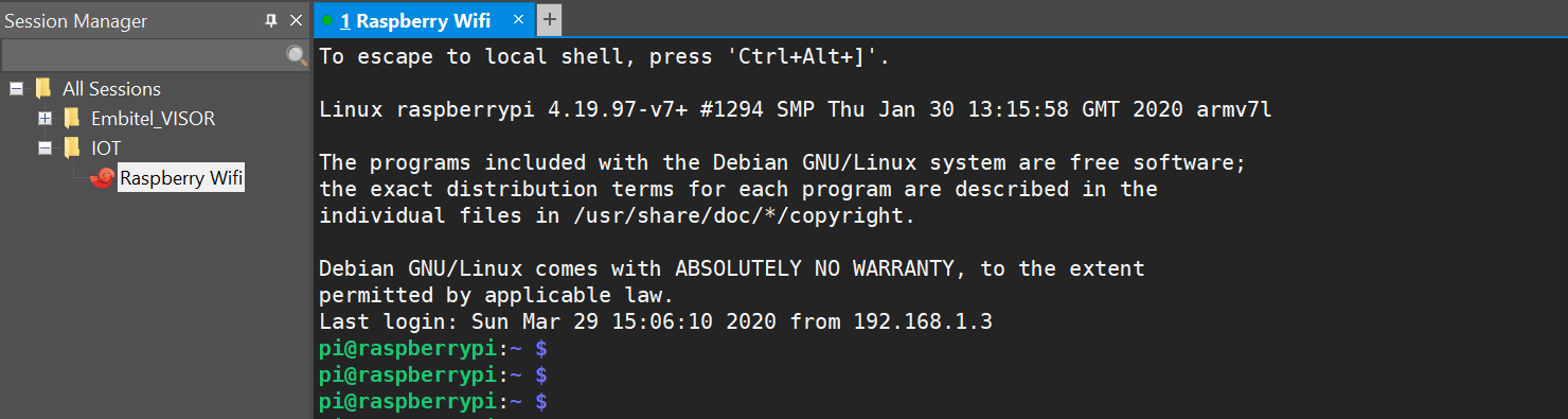
    Once you were able to connect via SSH you will be able to see below screen after a successful connection to Raspberry Pi.

    • Go to Desktop and create the new folder "DHT".
    • Now you can use the virtual environment to keep the installation local to the workspace instead of installing libraries into the raspberry pi system library which causes extra space and overload on the system.
    • Use below command to create the virtual environment for running the DHT Sensor Program to send sensor data to Google Cloud:
    pip install virtualenv
    virtualenv env
    source env/bin/activate
    •   Once successfully virtual environment is created you will be to below screen over the console.

    • Now run below commands to download and install the required package for creating device setup on the raspberry pi.
    sudo apt update && sudo apt upgrade
    sudo apt install git
    sudo apt install python
    sudo apt install build-essential python3-dev
    • Now download the DHT Adafruit library "Adafruit_Python_DHT", Python library to read the DHT series of humidity and temperature sensors on a Raspberry Pi.
    git clone https://github.com/adafruit/Adafruit_Python_DHT.git
    • Now install this library using the below command
    cd Adafruit_Python_DHT
    sudo python setup.py install

    After successful, this will build and install the library to the system.


    • Now go back to the previous folder "DHT" and download the program to publish the DHT sensor data to google cloud.
    (env) pi@raspberrypi:~/Desktop/IOT/DHT $ git clone https://github.com/sonwaneganesh/Sensor-data-to-google-cloud
    (env) pi@raspberrypi:~/Desktop/IOT/DHT $ cd Sensor-data-to-google-cloud
    (env) pi@raspberrypi:~/Desktop/IOT/DHT/Sensor-data-to-google-cloud $ export GOOGLE_APPLICATION_CREDENTIAL="/home/pi/Desktop/IOT/DHT/prefab-builder-267610-85095c6e6a55.json"
    (env) pi@raspberrypi:~/Desktop/IOT/DHT/Sensor-data-to-google-cloud $ export TOPIC_NAME="iot_sensor_dht"
    (env) pi@raspberrypi:~/Desktop/IOT/DHT/Sensor-data-to-google-cloud $ export PROJECT_ID=prefab-builder-267610


    • Before running the program we need to do some configuration for setting the Project details and Topic details using an export environment variable to system configuration. We have export TOPIC_NAME and PROJECT_ID details which have created using Google Cloud Console.
    • Additionally, you need to copy the downloaded service account JSON file to raspberry pi and provide the path the variable "GOOGLE_APPLICATION_CREDENTIAL"
    (env) pi@raspberrypi:~/Desktop/IOT/DHT/Sensor-data-to-google-cloud $ export GOOGLE_APPLICATION_CREDENTIAL="/home/pi/Desktop/IOT/DHT/prefab-builder-267610-85095c6e6a55.json"
    • Now download the DHT sensor code from my below git repo Sensor-data-to-google-cloud. Please follow the README file to update the DHT sensor and PIN configuration with Raspberry Pi.
    • You are ready to run our python program to send the sensor data by importing the google cloud and Adafruit DHT library function.
    (env) pi@raspberrypi:~/Desktop/IOT/DHT/Sensor-data-to-google-cloud $ python publish_dht.py
    • After this script will show the result data which have been sent continuously to the Google Cloud.

    • To verify whether data is on google cloud you can pull the data using subscription command on google cloud shell.
    • Run below command for pull data from the DHT sensor device.
    rakhishamkure@cloudshell:~$ gcloud pubsub subscriptions pull pub_sub_iot_sensor_dht --auto-ack --project=prefab-builder-267610 --limit=100
    • You will see the Data received on the google console successfully.


    Now we are able to see sensor data Temperature and Humidity from the DHT sensor connected to Raspberry pi is visible on the google IoT shell console.

    We have successfully able to send sensor data to the Google cloud environment where this information can be processed and analyze to take further different actions based on application we wanted to develop.
    Let's see one use case where if the temperature reaches a certain degree then we can turn on AC or FAN to maintain the conditional temperature environment in the room.

    In the next blog we will use Google Cloud service to control other devices, So please keep yourself updated with my blogs.

    SO please do like, comment and share this to make available to everyone are interesting in making such an interesting IoT project.


    Wednesday, April 8, 2020

    OK google! Turn on Light


    Let's begin with a small tutorial on how to control your home Bulb using the Google Voice assistance which you used in a Mobile device or smart TV at the home.

    Find below the Video link for the complete sequence to create this project at your home.


    Objective:

    With the Internet of Things, we can able to connect every device to the Internet and able to interact with it using the different services available over the internet. This device can be any sensor that can be able to generate any information in the form of an analog or digital signal. this device information can be used in different internet service using data communication and use available service to control these devices from the online service.

    Let's begin with the following sequence :
    • Installation of Arduino and ESP8266 configuration.
    • Adafruit IO service 
    • IFTTT applet service.
    • Hardware setup configuration.
    • Source code
    •  Demo
    Hardware Requirement:
    • ESP8266 NodeMCU 
    • Bulb
    • Relay Board (1 channel relay Board )
    • Breadboard
    • Jumper wire
    Software Requirement:
    • Arduino IDE.
    • Fritzing  
    Installation of Arduino software:

    The Arduino Software (IDE) allows you to write programs and upload them to your Microcontroller board used to connect any sensor device. 

    It easy to write code and upload it to the board. It runs on Windows, Mac OS X, and Linux. Please find the Software Download link for the windows. Now Install the Arduino Desktop IDE for windows using step-by-step instructions using my video reference. 


    Once you installed the IDE successfully open the Arduino program from the start menu. Connect your ESP8255 Nodemcu microcontroller board to PC using USB-Serail Port. The matching COM port will be shown in Ardunio SOftware when you connect the ESP8266 Nodemcu with the PC using USB-Serial Cable.

    Now you need to install the ESP8266 Board Package. 
    • Go to File -> Preferences from the Arduino Software.

    •  Add link http://arduino.esp8266.com/stable/package_esp8266com_index.json into Additional Board Manager URLs field in the Arduino preferences. 
    With this, we are adding this new ESP8266 microcontroller board to Arduino IDE. Next, use the Board manager to install the ESP8266 package. [Tools --> Manage Libraries -> Board Manager].

    • Install ESP8266 Nodemcu library using the "esp8266" key in the search bar.


    After the install process, you should see that the esp8266 package is marked INSTALLED. Close the Boards Manager window once the install process has completed.


    Blink Test :


    We'll begin with the simple blink test so it will make sure that our connection to the ESP8266 board is correct and working fine.

    
    void setup() {
      pinMode(LED_BUILTIN, OUTPUT);     // Initialize the LED_BUILTIN pin as an output
    }
    
    // the loop function runs over and over again forever
    void loop() {
      digitalWrite(LED_BUILTIN, LOW);   // Turn the LED on (Note that LOW is the voltage level
      // but actually the LED is on; this is because
      // it is active low on the ESP-01)
      delay(1000);                      // Wait for a second
      digitalWrite(LED_BUILTIN, HIGH);  // Turn the LED off by making the voltage HIGH
      delay(2000);                      // Wait for two seconds (to demonstrate the active low LED)
    }
    

    Build and upload the code to the connected ESP8266 Microcontroller. Once successful upload ESP8266 will start blinking its LED with a delay of 1 sec.

    Adafruit IO Service:

    Now we have configured ESP8288 with Arduino software we are ready for the next step to create service using the Adafruit IO service. Adafruit IO is the easiest way to get your projects onto the Internet of Things. Using Adafruit IO service you can connect your device our the internet service. Adafruit IO uses MQTT (message queue telemetry transport) as a transport protocol for device communication that Adafruit IO supports. 


    Adafruit IO: Feeds

    Feeds are the core of Adafruit IO which takes part in exacting data communication to and from Adafruit IO service. This feed data can be used to control the sensor device using the microcontroller device like ESP8266. Using an MQTT library or client you can publish and subscribe to a feed to send and receive feed data. you can read more from Adafruit IO site on how to create, edit, and delete your very own feed. 

    Adafruit IO : Dashboard

    The second part is Dashboards allow you to visualize and control Adafruit IO connected projects from any modern web browser. Widgets such as charts, sliders, and buttons are available to help you quickly get your project up and running without the need for any custom code.

    Adafruit IO Key:

    To use the Adafruit service over the internet we need a few connection details when establishing the connection to Adafruit IO service. use the following details to connect an MQTT client to Adafruit IO:
    • Host: io.adafruit.com
    • Port: 1883 or 8883 (for SSL encrypted connection)
    • Username: your Adafruit account username (see the accounts.adafruit.com page here to find yours)
    • Password: your Adafruit IO key (click the AIO Key button on a dashboard to find the key)
    Note: Your Adafruit IO Key should be kept in a safe place and treated with the same care as your Adafruit username and password.


    Below are the parameters which need to be set in the Arduino source code. 
      #define IO_USERNAME  "account_username"
      #define IO_KEY       "aio_key"


    IFTTT service:

    IFTTT ( If This Then That), is a web-based service that creates chains of simple conditional statements, called applets. An applet is triggered by changes that occur within other web services such as Gmail, Facebook, Telegram, Instagram, or any app service which can be used daily basis.
    With this you’ll have access to an ecosystem of over 600 world-class services, thousands of active developers and millions of consumers.
    Using applets we can able to connect the multiple services together and trigger any action based on the condition set to the trigger. For more details please go to the documentation page of the IFTTT site.

    Our applets will connect the Adafruit feed service to the google voice assistance service. For that, you need to register this service using your Google account details. With google voice assistance we can create the trigger to Adafruit using the trigger command set which can be done easily with IFTTT applet service. So we have created two applets to feed voice data for turning on light and turning off light to Adafruit feed we have created.


    Once we have created service ready we can able to start with setup details and coding part.

    Setup Diagram:


     Component Description:


    ESP8266 NodeMCU :

    NodeMCU is a low-cost open-source IoT platform. NodeMCU included firmware that runs on the ESP8266 Wi-Fi SoC from Espressif Systems. ESP8266 is a bite-sized and low const WiFi-enabled microcontroller, it can monitor and control things from anywhere in the world and it just perfect for just about any IoT project.
    Specification of ESP866 NodeMCU:
    • ESP-12E Chip Tensilica Xtensa® 32-bit LX106
    • 80 to 160 MHz Clock Freq.
    • 128kB internal RAM
    • 4MB external flash
    • 802.11b/g/n Wi-Fi transceiver
    Power to the ESP8266 NodeMCU is supplied via the on-board MicroB USB connector. Alternatively, if you have a regulated 5V voltage source, the VIN pin can be used to directly supply the ESP8266 and its peripherals.

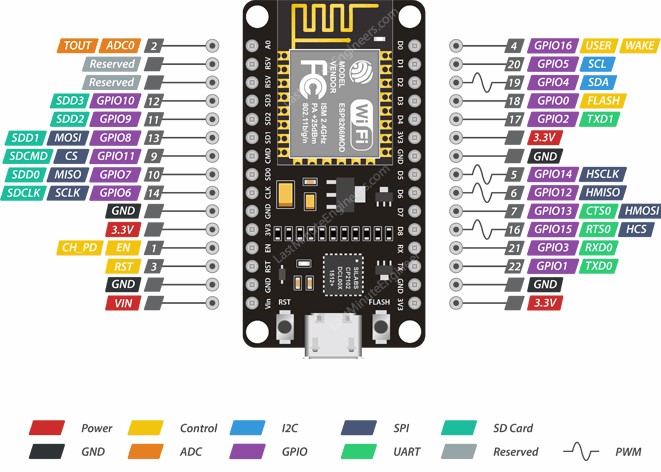
    The ESP8266 NodeMCU has total of 30 pins that interface it to the outside world. The connections are as follows:

    For more details please visit NodeMCU Link.

    Relay: A relay is an electrically operated switch and like any other switch, it can be turned on or off the electrical device. It can be controlled with low voltages, like the 3.3V or 5V which can be provided by the ESP8266 GPIOs and allows us to control high voltages like 12V, 24V or mains voltage 230V from home AC line. 

    Below is the Fritzing sket of the circuit diagram. You can download this from my git repo google-voice-assistance-with-ESP8266-nodemcu. 


    Here we controlling 230V bulb using the GPIO pin connected from ESP8266 Micontoller using Arduino code.  The two connectors (with three sockets each) on the left side of the relay module connect high voltage bulb, and the pins on the right side (low-voltage) connect to the ESP8266 GPIOs. 

    Connect D1 pin of ESP8266 to Relay to control as shown in the circuit diagram.


    Coding:


    • Download the source code from my git repository google-voice-assistance-with-ESP8266-nodemcu. 
    • Open ardino file ESP8266_BULB.ino using Arduino Software.
    • Edit the Wifi Credential to connect your ESP8266 device to internet service using local wifi connection.

    // WiFi parameters
    #define WLAN_SSID       "ssid" // use wifi ssid
    #define WLAN_PASS       "password" // use wifi password
    

    • Then edit the Adafruit connection Details described with Adafruit service.

    // Adafruit IO server details.
    #define AIO_SERVER      "io.adafruit.com"
    #define AIO_SERVERPORT  1883
    #define AIO_USERNAME    "username" // user username 
    #define AIO_KEY         "aio_key"  // use aio key Obtained from account info on io.adafruit.com
    

    • Build the code using Arduino IDE build command.
    • After Build successful Upload the code to connected ESP8266 NodeMCU using USB-serial cable. Arduino IDE will automatically upload the code to ESP8266. 
    • Then ESP8266 will reset itself and start running with uploaded code.
    • you can monitor the console log enabled in using connecting to serial monitor using Arduino IDE. 
    Now your home electric bulb is connected to your google voice assistance.  So you can start your google voice assistance mobile device and send the voice command which you have registered as a command to IFTTT applets.
    Visit below my youtube link here.


    I hope you enjoyed the small IoT project at your homeplace. Please provide your feedback about this project. Please do like, comment, and share my project to reach more people who wanted to learn such interesting projects.


    Saturday, February 22, 2020

    Using Google Cloud IoT Core Platform with a Raspberry Pi


    In this blog, I will explain how to connect our raspberry pi as a gateway device to google cloud IoT platform so that we can able to send our sensor data into a cloud environment.  We will use LED light as a sensor device to connected to Raspberry pi and then change the status of LED (ON/OFF) from the Google Cloud. This mean we can able to control our LED light connected to Raspberry Pi using the Internet of Things service provided by Google IoT cloud.

    This IoT project will connect you every sensor device from homes like TV,  Light, FAN and any other electronic appliance which you will be able to easily connect and control from the IoT service.

    Before going to much details you should have basic understanding of how Internet of Things works which can be explained in my blog Internet of Things. Then you need to understand how Google service Google IoT Core Platform allows us to fully manage IoT service in a very flexible and efficient way.

    Google IoT Architecture

    The following diagram gives an overview of the device/gateway architecture for use with the MQTT bridge.

    Basically, the gateway is a device that connects sensor devices to Cloud IoT core and performs serval tasks on the sensor devices' on behalf, such as communication, authentication, storage, and processing the information on the cloud environment. for more information about Google IoT cloud please find here in link Google IoT Cloud.


    In the previous blog, I have described the  Installation of Raspberry Pi and how to connect in the local wifi network using SSH connection (set up local WiFi and enable SSH on your Raspberry Pi). This will enable us to connect our raspberry pi to access internet service from global internet service.

    So let's begin with connecting our Raspberry pi as a gateway to google cloud platform.


    Required Hardware:
    • Raspberry Pi
    • LED
    • 10K Ohm Register
    • Bread Board and Jumper Wire 
    Required Software:
    • Git
    • Python
    • OpenSSL
    • Xshell


    Before going to hardware configuration lets begin with creating the google cloud platform for setting up the raspberry pi as Device gateway. Below are the steps used for configuring the device gateway and creating a device registry.
    • Create a Google Cloud Project
    • Setting up the local environment and installation process
    • Create Device registry and generate Device Keypair
    • Add a new device to registry
    This is above steps which can be found with the quick-start guide of the google could page:
    google iot quickstart

    Later we will extend this to our new feature for LED program for data exchange with Cloud.
    • Run an LED program to see telemetry from Gateway (Raspberry Pi) to Google IoT Core.
    • Update the Config data from Google IOT to toggle the LED status (ON/OFF) connected to Raspberry Pi.


    Create a Google Cloud Project:

    Go to Google Cloud Console, on the project selector page you can select or create the new project.

    Once the project creates go to page selector page go to select the created new project. You will be able to see the dashboard with all the project related information.


    In the Google Cloud IoT Console home page, you will be able to see the different products. Now we will enable the Cloud IoT Core and Pub/Sub API product from the home page. Please click the below link to enable to API.


    Once you enable the API, you will be able to use the API service with the Google Cloud Platform.

    Create Device Registry:

    Once the Google IOT project ready we will create the device registry. This device is a processing unit that is capable of connecting to the internet and exchanging the data with the cloud. This device registry is a container of devices with shared properties.

    Let start the below steps to create at least one device registry for this project.

    • Go to Google cloud console (Link) and click on the IoT Core tab in left navigation bar.
    • Click on Create Registry option available in the IoT Core menu. Give Registry ID "pi-registry".
    • Select the region associated with your location "asea-east1" and Select the MQTT protocol.
    • In the Default telemetry topic available in Cloud Pub/Sub Topics, create the new topic "gateway-telemetry" which can be use as a device topic to exchange the telemetry data (LED status). 
    • Optionally create topic "gateway-state" using Create Device state Field.
    • Leave the remaining option as it is and then click below Create button.


    you have just created the device registry with Cloud Pub/Sub topic for subscribing or publishing the telemetry message send between Gateway Device and Google IoT Core using MQTT Bridge.


    Now you need to create the "Device" which connects to the internet directly through Gateway.
    • Go to Created Device Registry "pi-registry" in the Cloud IoT Core tab.
    • Go to the Devices tab in the menu bar.
    • Create the device using "Create A Device" Button.
    • Create a device with Device Id "led-light" and keep the rest of the field as it is. you will be understood other things as you go further with other examples.


    So now we have created Device Registry "pi-registry" and Device "led-light" we can use this information in Device Gateway to communicate with the Google Cloud IoT platform.

    Lets now move to our Raspberry Pi device which we will use as the Device Gateway to communicate with the Google IoT core for data exchange related to the Sensor device (led light).

    If you are not aware of how to install raspberry pi and enabling the ssh communication then you can check my other blogs on the installation of the raspberry pi.


    Setting up Raspberry Pi as you Gateway:

    Here we will use Raspberry pi as the gateway device for the installation and setup process. 
    To Setup your gateway:

    • Connect with Raspberry pi. using SSH connection using a local Wifi network (Link).

    • Open the console terminal and install the required software dependencies.
    sudo apt update && sudo apt upgrade
    sudo apt install git
    sudo apt install python
    sudo apt install build-essential libssl-dev libffi-dev python-dev
    • clone the below repository into a local directory
    git clone https://github.com/GoogleCloudPlatform/community.git

    • go to the below directory structure
    cd community/tutorials/cloud-iot-gateways-rpi
    • Generate the RS256 Public/Private Key pair by running the following command.
    ./generate_keys.sh
          This will create the below key files in the current directory which can be used for a secure connection between gateway device (Raspberry Pi) and google IoT core. 
    1. rsa_private.pem (secrete key to be kept in the local machine only)
    2. rsa_public.pem (public key to be shared with a device which wants to have a secure connection with device gateway)
    • Provide the public key information with the Device registry created in Cloud IoT Core. To do that please follow the below steps:
    1. In Cloud IoT core click on the Registry, you created "pi-registry"
    2. Click on Gateway tab and then click "Create Gateway"
    3. Provide the Gateway ID "my-gateway"
    4. Copy the content of rsa_public.pem (from a raspberry pi local directory) into the public key area.
    5. Leave the rest of the field as it is and then click on Create.

    • Back to Raspberry Pi, Now export Google Cloud Project Id as Environment Variable by running following command. 
    export GOOGLE_CLOUD_PROJECT=your-project-id-123
    • Download the Google CA root certificate into the same current directory using the below command.
    wget https://pki.goog/roots.pem

    • Now set up is done here we will be updating the "run gateway" script by providing the details for registry_id,  gateway_id, cloud_reason, and project_id created before.
    python ./cloudiot_mqtt_gateway.py \
      --registry_id=pi-registry \
      --gateway_id=pi-gateway \
      --cloud_region=asia-east1 \
      --project_id=project-id-123\
      --private_key_file=rsa_private.pem \
      --algorithm=RS256 \
      --ca_certs=roots.pem \
      --mqtt_bridge_hostname=mqtt.googleapis.com \
      --mqtt_bridge_port=8883 \
      --jwt_expires_minutes=1200


    • Now you can use the virtual environment to keep the installation local to the workspace instead of installing libraries into the raspberry pi system library which causes extra space and overload on the system.
    • Use below command to create the virtual environment for running the Device Gateway:
    pip install virtualenv
    virtualenv env
    source env/bin/activate
    • You will be able to see the below (env) on the left side of the ssh console.

    • Now install the required package by using the below command.
    pip install -r requirements-gateway.txt
    • Now start the Device Gateway service by running below command.
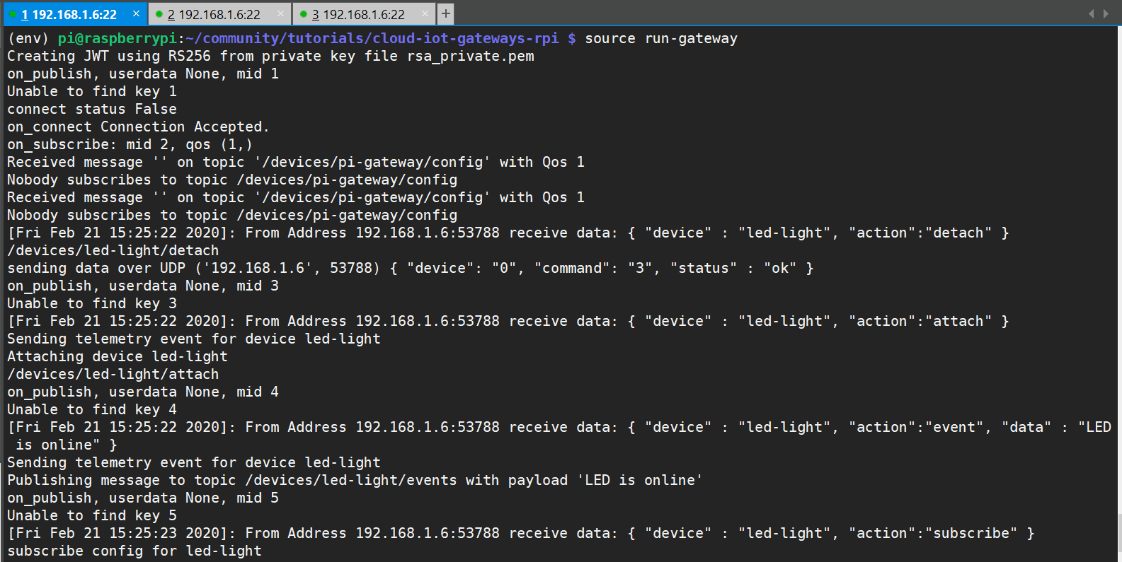
    source run-gateway


    Now keep this Gateway running on console separate SSH console. This will provide the interface to communicate created devices (led-light) to communicate with the Google IoT core.  


    The next part is to use the created "led-light" device to interact with the Gateway. Here we will connect LED light to Raspberry Pi via Ping 14 and Ground PIN. Below is the schematic of the LED connection.


    Now you can use the "run-led-light" script to update the LED switch using cloud communication.
    this script will update the LED switch based on the data coming from the Google IoT Core Device "led-light".


    Manage Device (led-light) Via Config Update:

    Now we will manage the LED light connected to Device Gateway (Raspberry Pi) though Google IoT Core config update.

    • Go to Google IoT Core console and click on registry created "pi-registry"
    • Click on the "pi-gateway" from the Gateway Tab in the registry.
    • Click on Bound Devices Tab
    • Click on Blind Device and then select the box next to "led-light"
    • Confirm by clicking Bind in the lower right.


    Once the device is successfully able to Bind. we are ready to run the script which will start sending and receiving the data from the cloud. Please find below the steps to run the device script from different console connected to a raspberry pi.
    • Go to raspberry pi ssh console and edit the led-light.py by adding the IP address of the Device gateway (Raspberry PI which already running as a gateway from the run-gateway script.) which is already running on Raspberry Pi.
    • Make sure you have already connected LED to Raspberry pi's GPIO pin 14 and ground using the appropriate register.
    • Run the following program from the Raspberry pi console  
    source run-led-light


    • Once the program runs it will start to show the status for LED like "Client received OFF".


    • Now your LED is connected to the Cloud IoT Core platform so you can update the device status from the Cloud IoT Console.
    • Go to Google IoT Console and select your Registry "pi-registry".
    • Go to devices and select the device "led-light".
    • Click on Update Config at the top of the page. Now you can able to communicate with the LED device by sending the message data for switching ON/OFF LED connected to the Raspberry Pi Gateway device.


    • In update Configuration show above you can able to send the using Test message, Enter ON or OFF to toggle the LED state which will reflect LED status connected to Raspberry Pi.


    All set then we will be able to see our LED light is getting toggle with each message. And that's how we can connect our LED light to the Google IoT Core platform successfully.

    Please try this exercise by yourself so that you will be able to enjoy the IoT project from my blogs.


    Next blog, I will be showing how we can attach multiple sensor devices to Raspberry Pi (Device Gateway ) and able to see the sensor data over the cloud environment in real-time.

    I hope you have enjoyed this blog, so please do like, comment and share this blog.


    Sunday, February 24, 2019

    Introduction to Raspberry Pi


    Hi everyone.

    Let's start something interesting with Raspberry Pi wonderful and powerful electronic device for IOT projects. This is a Raspberry Pi, small portable size computer in your hand. It is a single board computer developed by Raspberry Pi foundation educational and electronic project study in institutes. Please visit the Raspberry Pi site for more information 

    In this tutorial, I am going to provide the basic information about the Raspberry Pi which is a tiny and affordable computer that can be used to learn programming and interesting project on the internet of things (IoT) projects. 
    Raspberry Pi has many release version, first generation (Raspberry Pi 1 Model B) which was released in 2012, followed by other cheaper version with Model A support.  Raspberry Pi 3 Model B+ which is latest in all the Raspberry Pi model release in 2018. Their board is approximately credit card size which supported all the configuration need to as a personal computer. For information about all product you can visit official site of raspberry Pi.

    Now let's get deep details into configuration of the Raspberry  Pi 3 Model B+.

    Hardware Configuration:

     The Raspberry Pi 3 Model B+ is the latest product in the Raspberry Pi 3 range, boasting a 64-bit quad core processor running at 1.4GHz, dual-band 2.4GHz and 5GHz wireless LAN, Bluetooth 4.2/BLE, faster Ethernet, and PoE capability via a separate PoE HAT


    Please find the details of the Raspberry Pi 3 Model B+ specification.

    • Processor : Broadcom 64-bit SoC @ 1.4GHz
    • Memory: 1GB LPDDR2 SDRAM
    • Connectivity: 
          • WiFi 802.11.b/g/n/ac wireless LAN
          • Bluetooth 4. Gigabit Ethernet over USB 2.0
          • 4 × USB 2.0 ports

    • Video & Sound: 
          • HDMI port support
          • MIPI DSI display port
          • MIPI CSI camera port
    • SD Card Support: Micro SD format for loading operating system and data storage
    • GPIO Access: Extended 40-pin GPIO header
    • Input Power: 
          • 5V/2.5A DC via a micro USB connector
          • 5V DC via GPIO header
          • Power over Ethernet (PoE)–enabled (requires separate PoE HAT)
    • Environment: Operating temperature, 0–50°C


    General Purpose Input-Output (GPIO) connector:

    With Raspberry Pi GPIO pin we can able to communicate with external circuitry as the extension board. We can connect and interface the electronic circuits which are used in an embedded system using the Raspberry Pi GPIO interface


    More details about the interface and understanding the GPIO pinout can be at Raspberry pi pinout web page.

    Each pin has the functionality to carry the analog and digital signal to the external circuit and communication using controlled and configured interface.

    Using GPIO standard pin you can able to turn devices on and off such as LED light can be controlled using these GPIO digital pins.


    Along with the standard GPIO input-output pin some other interface communication is also supported by GPIO interface.


    • I2C (Inter-Integrated Circuit): pins allows you to connect and talk to any hardware module circuit that supported this I2C protocol communication. Example If we wanted to connect DHT (temperature and humidity) sensor to our raspberry pi it can use I2C interface to communicate with Raspberry pi.
    • SPI  (Serial Peripheral Interface Bus): pins can be used to connect and talk to SPI devices which usually used for data transmission between Raspberry pi to SPI supported devices such as SD card.
    • UART Universal Asynchronous Receiver/Transceiver):  it is the serial pin used to communicate with connected other devices.

    Software Support:

    Raspberry Pi can be loaded with various distributions of the operating system (OS).  Raspberry Pi foundation provides the Raspbian, Linux distribution as well as the third party Ubuntu, Windows 10 IOT Core, AndroidThings and many more based on your required platform for IoT.  this Operating system can be installed on SD card which can be used as the storage devices for operating system and applications.

    Once the operating system installed we will be able to access like home computer. There are multiple devices can be connected to Rasberry pi to access like the computer. We can connect Computer desktop using HDMI card, also we can connect the Mouse and Keyboard with a supported USB board.

    We can connect this raspberry pi device to our home network using the LAN port or using Wifi support. Once this device is able to connect to the internet we can also able to access the internet service using a raspberry pi.


    This is what Raspberry Pi is able to provide the most of the required functionality to start projects on IOT.

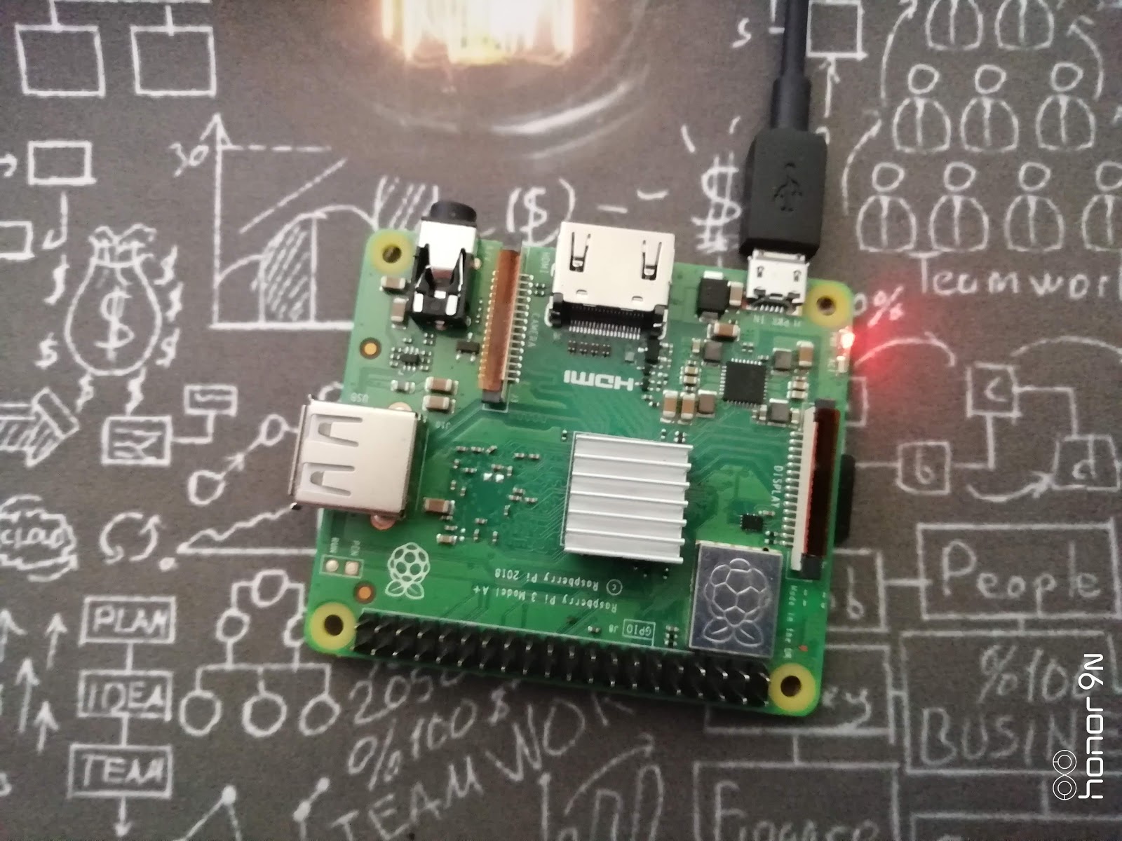
    This is the Raspberry Pi version which I have got from the Thingsbits online shopping which packed with power cable and USB cable. It cost me around Rs. 2540 Indian rupees which can be affordable for compared to a large computer system.


    Additionally, I ordered Heatsink to protect from heat due to the processor which can reach up to 85-degree Celsius to avoid the damage to my raspberry pi board.  

    Please watch this video about the introductoin of Raspberry Pi:


    So this is how I got this my first product of raspberry pi and seems very interesting to me with its design and compatibility.


    Smart Home Gardening solution with IOT

    Food is an essential part of day-to-day life. So with agriculture, we can cultivate the plant and made food for a living. We have a very ...