
In the last blog Sending Room Temperature and Humidity Data to Google Cloud, we have sent the room temperature and humidity data to google cloud using the Google IoT core platform. This makes us complete our first steps of connecting to the Google IoT cloud and send the sensor data from the device to the cloud. Now next step is to read those data from the Google cloud environment and put it into useful information or any kind of application that we wanted to control using these sensor data.
Here basic use case will be if the temperature of the room goes beyond a certain degree we can able to turn on the cooling devices.
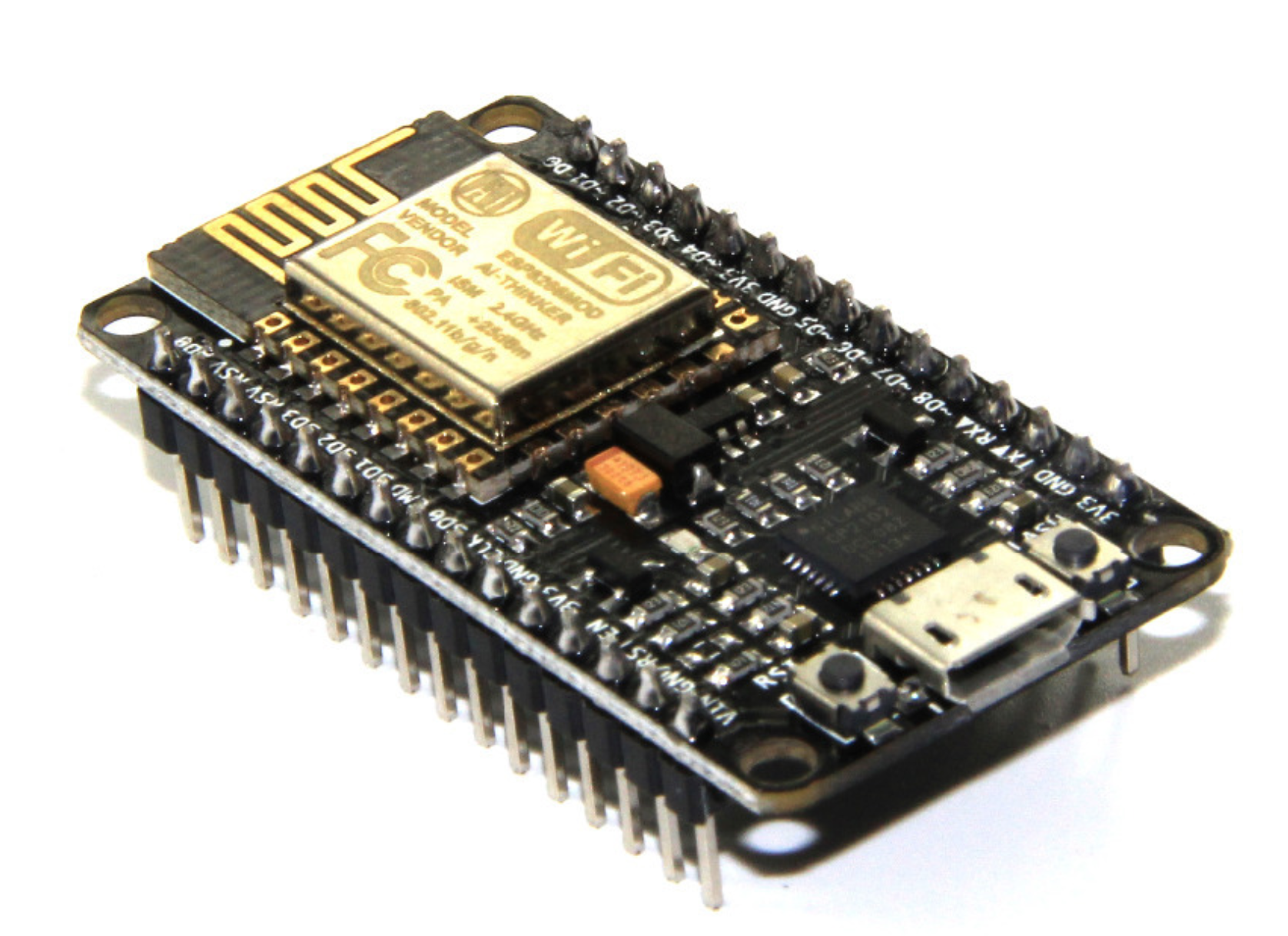
Here we will use the ESP8266 Nodemcu microcontroller to read the sensor data from Google Cloud.
 |
| https://en.wikipedia.org/wiki/NodeMCU |
Let's begin with the following sequence :
- Installation of Arduino and ESP8266 configuration.
- Library Configuration for Google IoT Cloud
- Hardware setup configuration.
- Source code
- Demo
Hardware Requirement:
- ESP8266 NodeMCU
- FAN
- Relay Board (1 channel relay Board )
- Breadboard
- Jumper wire
- Arduino IDE.
- Fritzing Software
Programming Language:
- C/C++
- Python
- OpenSSL Command line
Introduction:
ESP8266 NodeMCU :
ESP8266 NodeMCU is a single-board microcontroller and low-cost open-source IoT platform. NodeMCU included firmware that runs on the ESP8266 Wi-Fi SoC from Espressif Systems. ESP8266 is a bite-sized and low const WiFi-enabled microcontroller, it can monitor and control things from anywhere in the world and it just perfect for just about any IoT project.
Specification of ESP866 NodeMCU:

- ESP-12E Chip Tensilica Xtensa® 32-bit LX106
- 80 to 160 MHz Clock Freq.
- 128kB internal RAM.
- 4MB external flash.
- 802.11b/g/n Wi-Fi transceiver ()
Power to the ESP8266 NodeMCU is supplied via the on-board MicroB USB connector. Alternatively, if you have a regulated 5V voltage source, the VIN pin can be used to directly supply the ESP8266 and its peripherals.

The ESP8266 NodeMCU has a total of 30 pins that interface it to the outside world. The connections are as follows:

LCD Display with I2C Interface:
This I2C 16x2 Arduino LCD Screen is using an I2C communication interface. It means it only needs 4 pins for the LCD display: VCC, GND, SDA, SCL. We Will use the LCD display to display the sensor data temperature and humidity taken via ESP8266 Nodemcu.

You can get this display device from online Roboelements.com.
Sketch Diagram:
The below diagram shows the complete circuit connection for setting up the project. The LCD display will display the temperature and humidity data which is collected using the ESP8266 Nodemcu using the I2C interface. This display information will provide the current temperature and humidity details in-room environment.

Relay is to control the FAN when the digital signal received from the ESP8266 Nodemcu. This trigger is generated based on the temperature data i.e. if the room temperature reached above the threshold value (like 30% above) then FAN will get ON to cool the room temperature.
In Previous blog Part 1: Sending Room Temperature and Humidity Data to Google Cloud we are able to send the DHT data from the Raspberry PI to Google IoT Core.

From the previous blog, we have already created Device Registry "iot-sensor", pub/sub topic "iot_sensor_dht" and subscription "pub_sub_iot_sensor_dht" which collects the sensor data from device "" using the MQTT protocol.
Now, same sensor data we need to retrieve from the Google Cloud and send to other LCD display device using the ESP8266 Nodemcu. To-Do so we need to connect our ESP8266 Nodemcu to Google Cloud and fetch the data from Google Cloud using the MQTT protocol.

In this section, we will create another device to store the sensor data for ESP display and then send this device data to ESP8266 using the MQTT over this device. To store the data inside this new device we all create the Cloud function which will read the data from the DHT device and send the related temperature and humidity data to the new ESP device using Cloud Pub/Sub mechanism. This cloud function will ensure that whenever DHT device sends the sensor data to the cloud it will trigger the cloud function to store the result data in the new ESP device
To connect the ESP device to Google Cloud we need to generate the certificate which can be used to secure the communication between IoT core device to the ESP8266 Nodemcu program.
Objective:
- Generate the Encryption certificates using the OpenSSL command line.
- Create a Device topic for ESP8266 "iot_sensor_esp".
- Create a Cloud Function to store data to a new Device topic.
- Logging Cloud function events.
Generate Encryption certificates:
To generate the certificate we will use the Google Cloud Console platform. use the OpenSSL utility to generate the ECC certificate using the below commands.
openssl ecparam -genkey -name prime256v1 -noout -out ec_private.pem
openssl ec -in ec_private.pem -pubout -out ec_public.pem


Keep both certificates at a secure place to avoid the disclose your account settings.
Create a new device topic :
- Go to google cloud IoT page in the Google cloud console (Link).
- Then go to the "IoT Core" tab available in the left navigation bar.
- Click on the created Device registry "iot_sensor" and then click on Devices tab.
- Click on "+ Create Device" under Devices Tab.

- Create a device with Device Id "sensor_esp_display" as display device for sensor data.
- The upload generated a Public key certificate in the Authentication Field using the upload option. Then click on the "create" button to finish the device creation. Keep the rest of the field as it is.

Now you will be able to see the new "sensor_esp_display" device under the device tab. So we have successfully created the new display device for LCD.
Create a Cloud Function to store data to a new Device topic:
Cloud Functions is Google Cloud’s event-driven serverless compute platform. Run your code locally or in the cloud without having to provision servers. We will use this funciotn to read the device "sensor_dht" and send the temperature and humidity information to device "sensor_esp_display".
To add the cloud function follow the below steps:
- Go to Google cloud console (Link).
- Then go to the "Cloud Function" tab available in the left navigation bar.

- Then click on the "Create Function" button in the Menu field.
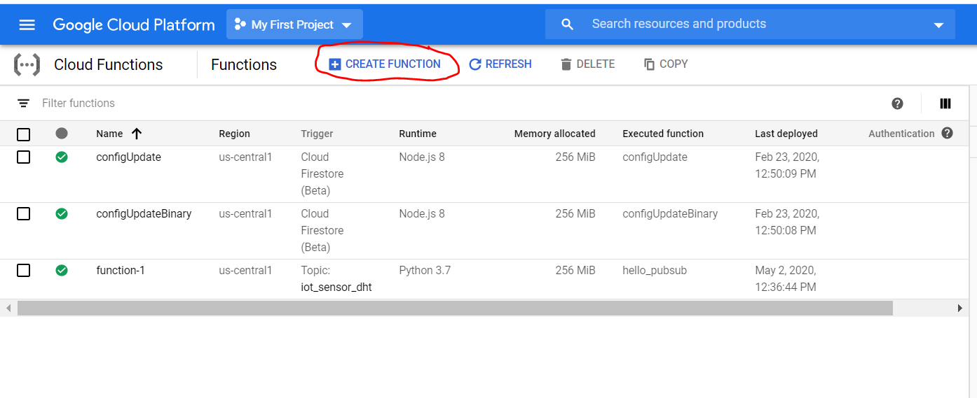
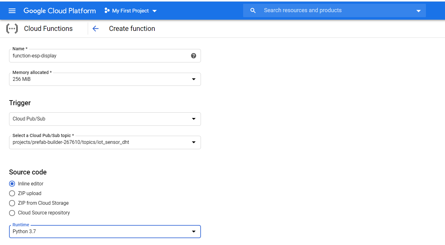
- Then provide Name "function-esp-display" to cloud function and remaining field details as shown below figure.
- Then we will add source code from python Main.py (source code link) content from the git repo to the Source code portion. Thin function run by google cloud when device "sensor_dht" data is updated.
- Also, update the REQUIREMENTS.TXT with python dependency.

- Add the below environment variable and click on the deploy button.

After successful deployment, we will able to send the DHT sensor data to the ESP display device.
Now let's begin with reading the sensor data from google platform using the ESP8266 Nodemcu which then can control FAN and display devices using Arduino programming.
Installation of Arduino software:
To configure and setup ESP8266 we need to download and install the Arduino software. Please download and install the Arduino software from the link Arduino Software.
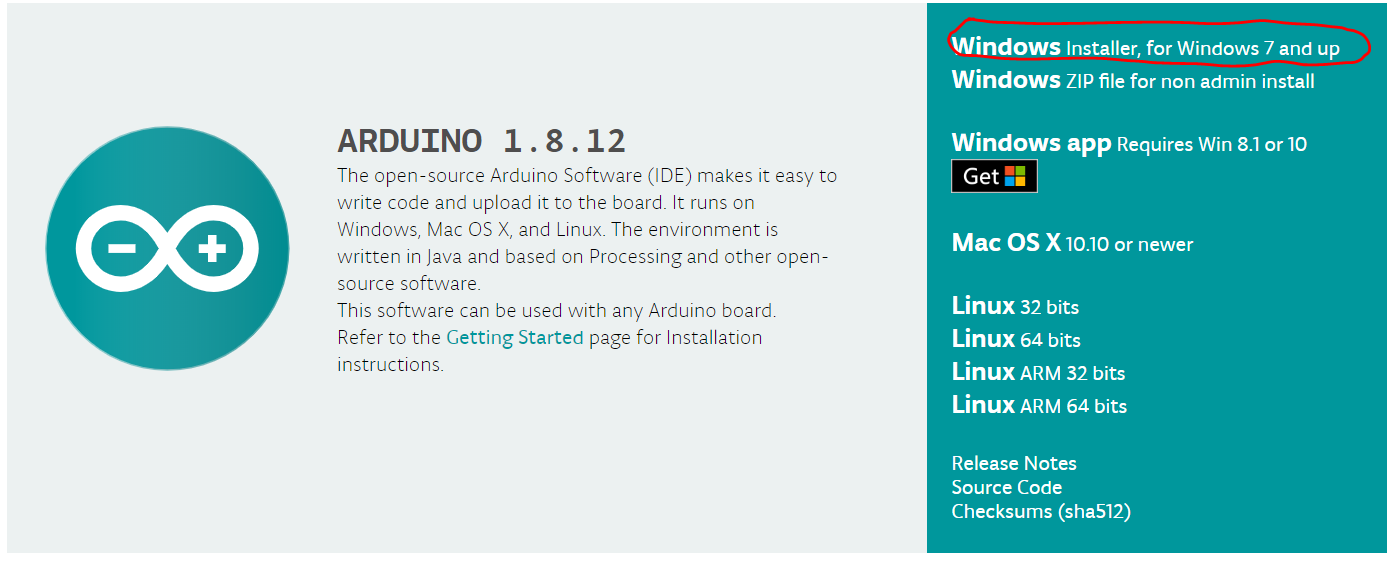
Click on the Highlighted portion to download the window installer. Open the downloaded installer and install the Arduino software with system admin settings. Once you successfully install Arduino you will be able to open Arduino Application from the start menu.
Once you installed the IDE successfully open the Arduino program from the start menu. Connect your ESP8255 Nodemcu microcontroller board to PC using USB-Serail Port. The matching COM port will be shown in Ardunio SOftware when you connect the ESP8266 Nodemcu with the PC using USB-Serial Cable.
Now you need to install the ESP8266 Board Package.
- Go to File -> Preferences from the Arduino Software

- Add link http://arduino.esp8266.com/stable/package_esp8266com_index.json into Additional Board Manager URLs field in the Arduino preferences.
- Open Board manager to install the ESP8266 package. [Tools --> Board (esp8266 Module) -> Board Manager]. Make sure your ESP8266 is connected to PC using USB cable.

- Install ESP8266 Nodemcu library using the "esp8266" key in the search bar.

- After the install process, you should see that the esp8266 package is marked INSTALLED.
Now we need to install the Google IoT Core library which will help in connecting the ESP8266 device to the Google Cloud IoT Platform. To install the library we need to open the library manager
- Go to Libary Manager. with path [Tools --> Manager Libraries -> Libary Manager].
- Install the "Google Cloud IoT Core JWT" Library using the below search key "Google iot cloud" in the search bar.

- Close the Boards Manager window once the install process has completed.
Now libraries are installed we are ready to get the run source program to connect the Google IoT core and display sensor information to LCD display.
Coding:
- Download the source code from my git repository Reading-Sensor-Data-from-Google-IoT-Cloud.
- Open Arduino file Google_IOT_Sensor_ESP.ino using Arduino Software.
- Edit the file credentials.h with wifi credentials to connect your ESP8266 device to internet service using local wifi connect
- Also, edit the Google Cloud project parameters which are created with Google IoT Console.
// WiFi parameters
#define WLAN_SSID       "ssid" // use wifi ssid
#define WLAN_PASS       "password" // use wifi password
#define PROJECT_ID  //"<Your Project ID>"
#define REGION  //"<Your Project's Region>"
#define REGISTRY  //""<Your Registry name>"
#define DEVICE  //"<Your device name>"
- Now update the Certificate private key in which we have created with OpenSSL from Google Cloud shell Console.

- Copy above private key content to the Arduino file "ciotc_config.hpp".

- Once after updating the Project and Key details we build the code using Arduino IDE build command.
- After Build successful Upload the code to connected ESP8266 NodeMCU using USB-serial cable. Arduino IDE will automatically upload the code to ESP8266.
- Then ESP8266 will reset itself and start running with uploaded code.
- you can monitor the console log enabled in using connecting to serial monitor using Arduino IDE.
Now Arduino code is running we can see that LCD display will show the temperature and Humidity data fetch from the DHT sensor connected to Raspberry Pi. Make sure the Raspberry Pi is running the python program which publishes the Sensor data to Cloud. (Please see the Previous Blog to make sure your DHT sensor is sending the data to Cloud.)
Logging Cloud function events:
You can log the Cloud sensor data using the below command on Google Cloud shell console. Please run below command to check the data on device "sensor_esp_display".
(prefab-builder-267610)$ gcloud functions logs read function-esp-display
Let's see the Sensor Data from DHT connected from Raspberry Pi to LCD display connected ESP8266 Nodemcu using Google IoT.
Now you have successfully done all this so if you have successfully connected the sketch diagram correctly then you will be able to LCD will start showing the Sensor data temperature and Humidity.
I hope you like the this blog. Please do like, comment, and share this post to everyone who are interested in the IoT project.


No comments:
Post a Comment